
|
| ... | The NEURAL CODE DECODED, DESCRIBED & DETERMINISTIC |
... |
This is the second of three closely associated pages discussing 1)the overall phasic stage (stage 3) of neural signaling , 2)the encoding of analog neural signals as action potentials and the resultant neural code, and 3)the recovery of the original analog signal from the encoded pulse stream (action potential stream).
The INTERNET contains an endless range of discussions concerning the decoding of the neural code. Many of these are based more on philosophy than neuroscience. Many are presentations by lower level academicians to naive students. Assertions are frequently made that the neural code is probabilistic, is Bayesian, or involves a "rate" code. None of these assertions is factual.
In fact, the neural code has already been decoded and described in significant detail. It is important to recognize neural signaling occurs in both the analog and pulse domains. Both the analog and pulse neural codes are totally deterministic.
The pulse neural code is more sophisticated than a simple rate code. A rate code requires multiple pulses to establish a rate. The pulse neural code is a place code. A single pulse (action potential) carries information in the place code used in the neural system. In electrical engineering terminology, the place code is a phase code. The phase code used in the neural system is known as a time-delay type of pulse position code. This time-delay code is particularly easy to generate and decode by simple neural circuits.
The details related to the neural code are available in Standard 106-96 of the IRIG (Inter-Range Instrumentation Group) that used this type code for decades prior to the availability of digital computers. The Standard may be hard to locate as it is now archaic in rocket testing.
The following material is broken into five sections:
Background required to understand the origin of the place code
The Operation of the coding ganglion neurons
The neural place code used in monoolar amplitude encoding pathways
The neural code used in bipolar amplitude encoding pathways
The Transfer function of ganglion neurons used in these pathways
Confusion between the action potential and S potential waveforms
In the electrophysiology laboratory, confusion has arisen between the always positive going action potentials and what appears to be a negative going version frequently labeled an S potential. The true action potential is typically obtained using intracellular recording from the axoplasm of the stage 3 neuron or one of its axon segments. The S-potential is typically recorded intercellularly by placing a probe alongside the neuron of interest near its soma (more specifically adjacent to the hillock). The signal voltage recorded at this location is that of the poditic terminal current leaving the neuron times the resistive impedance of the surrounding fluid. The pre-threshold waveforms related to these two signals are significantly different in polarity and amplitude and the amplitude of the monopulses are significantly different in amplitude as well as in polarity. Additional details of these signals are available at S Potential of Signal Projection Neurons
Discovering and elucidating the neural code of biology requires;
Based on these requirements, it can be shown that;
The visual modality provides a comprehensive, and well understood, exemplar of the neural system. The modality makes effective use of analog signal processing between the stimulus and the phasic encoding circuits and additional signal manipulation following phasic signal decoding.
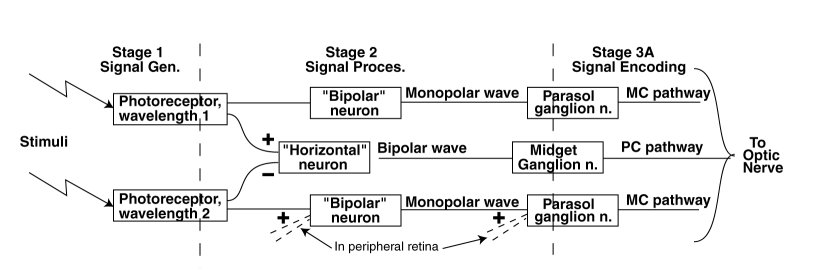
The figure shows the unique elements in the two types of fundamental paths through the foveola of the retina. The path through the bipolar neuron is a non inverting signal path leading directly to the optic nerve. The path through the horizontal neuron is a differencing signal path wherein one of the signals is inverted while the other is not. There are other neurons within the retina, typically labeled amercine neurons, which are of secondary interest here.
The paths through the peripheral retina generally involve additional summations as shown by the dashed lines in the figure. While important, this additional processing tends to complicate the operation of the system and reduce the spatial resolution of the retina (essentially tracking the reduced spatial resolution of the optical system.
The photoreceptor neurons are internally complex and include both the sensory function and a significant signal processing function. The signal processing function includes a (photonic) lightness to a (electrolytic) brightness conversion that is highly non linear in amplitude and converts an external signal of over seven orders of magnitude to a range of less than 200:1. It is also asymmetrical in time with what appears to be a very rapid attack time constant and a much slower decay time constant. The attack time constant is actually the difference between two distinct time constants. The signal processing function also includes a significant bandwidth limitation.
The signal processing between the output of the signal generation neurons and the input to the ganglion neurons is typically minimal. The bipolar and horizontal neurons do not limit the bandwidth of the signals. The horizontal neurons do invert the signal associated with one of its inputs.
The ganglion neurons frequently incorporate an analog signal processing function prior to the encoding of the analog signals into phasic pulse trains (action potentials). This function is generally described as a lead-lag network. Such a network can emphasize the transient response of the signal path relative to the stimulus.
Stage 2 Signal processing within the foveola (central 1.2 degrees diameter of retina) is complex, it includes;
The historical nomenclature based on morphology is awkward. The morphological bipolar neuron has an output (and input) that are electrolytically monopolar. Conversely, the morphological horizontal neurons have an input that is electrolytically monopolar but an output that is electrolytically bipolar.
The historically labeled parasol neurons (frequently labeled pc for parasol cell) connect to the magnacellular pathway (frequently labeled mc), while the midget neurons (frequetly labeled mc for midget cells) connect to the parvocellular pathway (frequently labeled pc).
The eyes of the sophisticated vertebrates exhibit a continuous fine motion defined as tremor. This angular motion exhibits an amplitude exceeding the diameter of the photoreceptors of the retina and a dominant frequency on the order of 90 Hertz.
The ever-present tremor of the eyes is critically important to the signals generated by individual photoreceptors. The signals generated within stage 1 are modulated significantly by the interaction of the spatial content of the stimulus and the tremor associated with movement of the eyes. The frequency of the resulting modulation is high, typically in the 60-150 Hertz region.
Spatial modulation plays a significant role in the brightness channels associated with the parasol ganglion neurons. It does not play a significant role in the chrominance channels associated with the midget ganglion neurons as shown below. Spatial modulation due to tremor can be eliminated by using Ganzfeld illumination as a stimulus.
The structure of the fundamental path changes in the periphery of the retina where multiple sensory signals are summed at either the bipolar neuron or the ganglion neuron (as shown symbolically at the bottom of the figure). Because of reduced lens resolution in the periphery, the affect of spatial modulation is greatly reduced.
The encoding neurons of biology are described here functionally (and electrolytically) as ganglion neurons. These neurons all exhibit a common internal electrolytic circuit that can be biased into either of two conditions. Those ganglion neurons processing monopolar signals are biased to operate as driven monopulse oscillators. Those ganglion neurons processing bipolar signals are biased to operate as free-running monopulse oscillators. Both types of oscillators generate a phasic pulse exhibiting only one stable (rest state). They do not exhibit two stable states as in binary encoding circuits. As a result, their output is optimized for signal propagation. Their output is not suitable for shift register operations or other binary pulse signal processing.
Frame (a) of the following figure illustrates the electrolytic circuitry of the ganglion neuron using standard electronic symbology. It is an expansion of the circuitry shown in the previous page of this subject set. Every ganglion neuron contains an active electrolytic device (within the circle) known as an Activa.
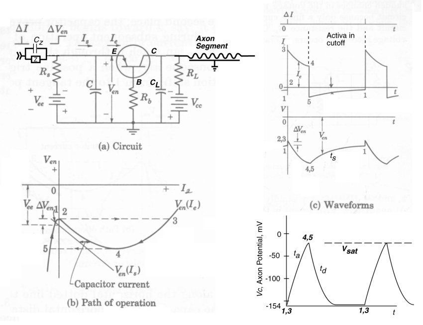
As indicated, the ganglion neuron operates with a negative voltage (Vcc, nominally -154 mV) applied to the axon terminal of the Activa. The Activa is a three terminal PNP type junction device in electrical engineering terminology. The dendritic terminal of the Activa is known as the emitter (E), the poditic terminal is known as the base (B), and the axon terminal is known as the collector (C). In electrical terminology, a conventional signal current flows from the emitter (more positive relative to the base) terminal to the collector (more negative relative to the base) terminal of the Activa when the device is in its active mode.
Notice the serial combination of the two parallel circuits, Z & Cz of the preceding synapse and Rs & C of the dendritic circuit. These elements form a lead-lag network in electrical engineering terminology. Their precise values can significantly affect the shape of the leading edge of the voltage pulse supplied to the emitter terminal of the Activa.
The operation of the ganglion neuron is critically dependent on the feedback impedance (Rb) connected between the base terminal of the Activa and the external poditic terminal of the neuron. This impedance provides internal positive feedback between the axon circuit and the dendritic circuit. This feedback causes the emitter circuit to exhibit a negative impedance characteristic as shown in frame (b)(a region of the curve slopes downward to the right). As a result, the overall circuit can be made to oscillate in a variety of ways.
In the case of the monostable parasol ganglion neuron, the method of choice is for the oscillation to be controlled by the dendrite capacitance, C and for the dendrite bias voltage (Vee) to be only slightly more negative than the voltage across the feedback resistance, Rb. In the absence of any stimulus via the synapse, the circuit is quiescent at point 5. Making the emitter more positive by DVen causes the circuit to be unstable and the current, Ie, to immediately increase to its saturation value as shown in both frames (b) and (c). Ie decreases along the transfer function to point 4 where it immediately jumps to point 5. It then proceeds slowly back to the quiescent level at point 1 (or point 2 if the stimulus from the synapse is still present).
The upper graph of frame ( c) shows the current flow into (Is) and out (Ie) of capacitor C. The middle graph of frame ( c) shows complete waveform of Ven The lower graph shows the voltage (Vc) at the collector, or axon terminal. The rising portion of the collector voltage is due to the current through the Activa ( Ic = Ie) charging the capacitor, CL. The precise shape of this current is controlled by the lead-lag network described above. To the extent the collector current, Ic is of constant amplitude, the slope of the collector voltage waveform is a straight line between points 3 and 4. In general, it is not an exponential waveform and the time constant, ta, is only an approximation. However, the time constant, td is a proper parameter of the collector voltage decay characteristic.
During the interval from point 5 to point 1, the neuron is in the refractory state. It takes a larger stimulus to raise the voltage Ven to the threshold voltage value of point 2.
The action potentials generated by the ganglion neuron are highly asymmetrical and their time constants are very temperature sensitive. Section 7.3.2 of Processes in Biological Hearing illustrate these sensitivities using excellent data from Schwarz & Eikhof.
The ganglion neuron is a switching-type oscillator. The currents and equations leading to the attack portion of the output circuit waveform are different from those leading to the decay portion of the circuit. The basic assumption by Hodgkin & Huxley that the waveform is based on a single set of equations between point 3 and point 1 is in error.
An increasing positive potential to the dendritic terminal relative to the poditic terminal, or to the external neural environment (or matrix), constitutes a larger stimulus to such a device. The following figure from Berry & Pentreath, and the previous webpage of this set, shows the result of stimulating the dendroplasm with a large step function. The numbers correlate with those in the figure above.
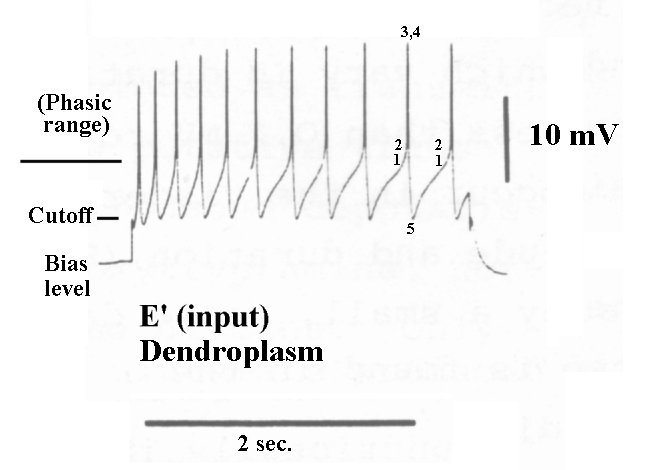
The excitation was a square wave beginning at a very negative artificial bias level. The voltage of the dendroplasm rises vertically in the high impedance region below cutoff. Upon reaching cutoff, the dendroplasm potential rises rapidly, due to the lower impedance of the Activa in the active regime, until it reaches the phasic threshold. Above the threshold, the circuit enters the phasic or oscillatory regime. An action potential is immediately generated, and the dendroplasm is discharged back to the cutoff potential. If the stimulus remains above cutoff, the cycle repeats itself and another action potential is generated. The time between the stimulus driving the dendroplasm potential above cutoff and the time threshold is reached is indicative of the strength of the stimulus. The closeness of the early action potentials suggests the input circuit incorporates a lead-lag network arranged as a pre-emphasis circuit.
If the bias of the dendroplasm of the ganglion neuron is at the cutoff level, the circuit will be much more sensitive to small stimuli. The first action potential will be generated as soon as the dendroplasm potential (the integral of the stimulus above the cutoff level) reaches the threshold value. Subsequent pulses will be generated at time intervals determined by the integral of the stimulus following the first pulse. Thus, the pulse interval will shrink for higher stimulus levels and expand for lower stimulus levels. See the following section on the transfer function of the ganglion neuron.
The output signal of such a device, in response to a positive going stimulus, is a positive going waveform of about 100 mV amplitude, relative to the quiescent axon potential of about -154 mV.
It is clearly seen that the output of the ganglion neurons is totally deterministic. They represent a state-variable circuit, whose output is totally defined relative to their input signal. They exhibit a refractory period that is typically unimportant in their in-vivo application since the input signal is typically bandlimited by the preceding circuitry. The refractory period can be illustrated in the laboratory using abnormal stimulation.
The optimum parasol type (monopolar input) ganglion neuron should show maximum sensitivity to stimuli without introducing significant noise into the neural pathway. This condition calls for the quiescent emitter (dendrite) voltage, Ven(quiescent), to be more negative than but as close as practical to the cutoff voltage labeled point 2. This maximizes the dynamic range available for the signal, between cutoff and saturation and accepts the generation of an occasional extraneous action potential due to analog noise.
The pulse train(s) generated by parasol type (monopolar input) ganglion neurons are described in the engineering literature as representing time-delay encoding or modulation. Time-delay encoding is a form of pulse position modulation (PPM). This type of modulation is characterized by packing more information into a given signal space than nearly any other form of modulation. Time-delay encoding is a more sophisticated form than a simple rate-based code. It is a place code. The time-delay encoding used in biology generates an initial pulse that occurs earlier the more intense the stimulus. Subsequent pulses occur closer together for higher intensity stimuli, as in rate-based coding. This performance is opposite to many man-made implementations of PPM.
The time-delay code used in the neural system is a (temporal) place code and not a rate code. The time of occurrence of the first pulse is relevant and provides important information related to the intensity of the stimulus. The time interval before the next pulse decreases linearly in proportion to the stimulus amplitude during the that interval. The reciprocal of this interval, the pulse rate, is not linearly related to the stimulus and is in fact assymptotic.
If the lead-lag network of a ganglion neuron creates a flat frequency pass band from the sensory neuron to the ganglion Activa, the first action potential departs from its quiescent level immediately upon the input exceeding the threshold level of the circuit. This initial pulse is used as an alarm mode signal in the subsequent circuits of stage 4. Subsequent pulses occur with a decrease in time delay that is linearly proportional to the amplitude of the stimulus above threshold.
In typical laboratory experiments, the parametric excitation of a ganglion neurons employs a constant current source that charges the input capacitor, C. The result is an emitter to ground voltage that is a linear ramp up to the threshold level. The capacitor is discharged during the pulse interval and the ramp begins again. This is the condition seen between points 5 and 2 in the above dendrite potential waveforms.
More details related to time-delay modulation in monopolar neural circuits can be found in Section 14.2.2 of "Processes in Biological Vision."
If care is taken in experiment design, it is possible to ensure a simple bandlimited step input to the encoding portion of the stage 3 ganglion neuron(s) associated with monopolar signals (such as brightness). The absolute voltage levels relative to the neural matrix and the polarity of the step are significant. The transient performance will vary with this polarity.
The optimum midget type (bipolar input) ganglion neuron should accomodate the largest amplitude bipolar signal without causing significant distortion. This condition calls for the quiescent emitter (dendrite) voltage, Ven(quiescent), to be in the middle of the dynamic range between the emitter cutoff and saturation voltages. As a result, the same ganglion circuit as used for the magnocellular pathways is biased to provide a continuous series of action potentials that can be phase modulated to encode the amplitude information associated with the bipolar analog stimulus.
Being a place code, the action potential stream generated by the ganglion neuron will exhibit a discontinuity very near the time of any major change in the stimulus. However the value of that change may not be apparent until the next clearly defined time-delay interval (between the subsequent two pulses). This fact has long been recognized in the electrical engineering community and it is memoriallized in both the NTSC and PAL analog color television standards. As in these systems, the neural system uses the positive region of the bipolar signal to encode "green" information and the negative region to encode either "blue" or "red" information (there are two chrominance channels in the large mammals).
If care is taken in experiment design, it is possible to ensure a simple bandlimited step input to the encoding portion of the stage 3 ganglion neuron(s) associated with bipolar signals (such as chrominance). Being a bipolar channel, the absolute starting and ending voltage levels of the step relevant to the neural matrix are significant. It is frequently desirable to generate a monopolar stimulus starting from the nominal quiesecent level of the input circuit.
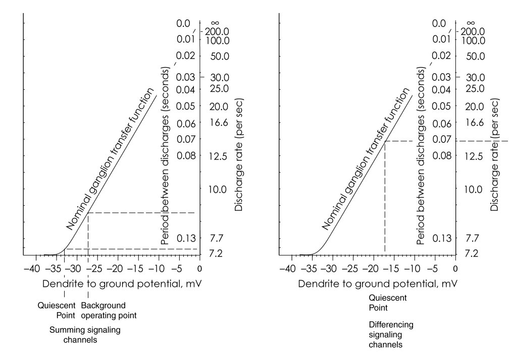
The following figure shows the nominal transfer function for the ganglion neuron; biased for monopolar operation on the left and for bipolar operation on the right. Note the linearity of the transfer function with respect to time delay interval. Conversely, the transfer function is highly nonlinear (in fact assymptotic) with respect to the rate of action potential generation.
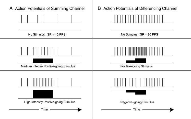
The following figure provides simple examples of signal encoding. The left frames show the typical quiescent condition at the top (output above the related input), a phasic signal resulting from stimulus by a constant amplitude analog signal, and a phhasic signal resulting from a higher amplitude analog signal. In both cases, both analog signals cause a first phasic action potential very near the start of the analog signal.
The right frames show a more complex situation. The top frame shows a constant phasic signal in the absence of any analog input stimulus. The middle frame shows the phasic response to a two-step positive-going analog stimulus, while the lower frame shows the response to a two-step negative-going analog stimulus. In both cases, a change in the pulse spacing occurs with the start of the analog waveform. Note that large negative going analog signals can drive the resulting phasic signal to very long pulse-to-pulse spacings. These long intervals greatly restrict the transfer of information by the system.
The maximum action potential pulse rate is difficult to specify. Under in-vivo conditions, the maximum rate reported in the literature is typically above 200 but less than 500 pulses per second. Under in-vitro conditions, and particularly parametric excitation conditions, rates up to 900 pps have been reported. However, it is not clear that these high rates are significant and can be decoded without distortion by the stellite neurons discussed in the following webpage of this subject set.
Go to the first (preceding) page of this subject set.
Go to the third page of this subject set.
Return to the Neuron Research home page.
Fulton, J. (2010) Neuron and Neural System Processes. Signal Projection Chapter. http://neuronresearch.net/neuron/document.htm
Berry, M. & Pentreath, V. (1978) The characterised dopamine neuron in Planorbis corneus In Osborne, N. ed. Biochemistry of Characterised Neurons. NY: Pergamon Press pg 89
Schwarz, J. & Eikhof, G. (1987) Na currents and action potentials in rat myelinated nerve fibres at 20 and 37 Celsius. Pflugers Arch. vol. 409, pp. 569-577
Cole, K. (1968) Membranes, Ions and Impulses: A Chapter of Classical Biophysics. Los Angeles, CA: University of California Press
Hodgkin, A. (1951) The ionic basis of electrical activity in nerve and muscle Biol Rev vol. 26 pp 339-409
Taylor, R. (1963) Cable Theory in Nastuk, W. Ed. Physical Techniques in Biological Research, Vol. 6. NY: Academic Press